¶ Powering ON:
When the Console powers ON, a notice dialog will pop up showing the valid credentials as a client of SWRM. The notice dialog will automatically close after several seconds.
- The Close button may be pressed to close the dialog early.

This is an example of a typical SWRM Console Display:

¶ Sensor Tabs:
Sensor Tabs are located in the upper left of the display. The Selected Tab is always shown first, followed by one additional tab for each connected SWRM Sensor Board. In this example, there are three Sensor Board Tabs.

¶ Selected Tab:
The purpose of the Selected Tab is to display only chosen Gauges from any of the available Sensor Board Tabs. These Gauges may be from any Sensor Board that is paired to the Console. Only Gauges that have been added to the Selected Tab will be displayed. The purpose of this is to keep your most important data available at a glance since only 12 Gauges can be displayed on the screen at a time, and to view data from more than one Sensor Board at a time.
¶ Adding Gauges to the Selected Tab:
To add a Gauge to the Selected Tab:
- Open the Sensor Board Tab that contains the Gauge that you wish to display on the Selected Tab.
- Press and hold the Gauge that is to be added for 1 second.
- When the Gauge moves at your command, drag it to any edge of the display.
- The display will change to the Selected Tab, with the Gauge added to the last position.
Notes:
- Gauges on the Selected Tab show which Sensor Board Tab it belongs to in its title.
- Gauges will be displayed in the order they are added to the Selected Tab and cannot be rearranged.
¶ Removing Gauges from the Selected Tab:
To remove a Gauge:
- Press and hold the Gauge that is to be removed for 1 second.
- When the Gauge moves at your command, drag it to any edge of the display.
- The Gauge will disappear and is successfully removed.
Note:
- Gauges can only be removed from the Selected Tab.
¶ Sensor Board Tabs:
All other Sensor Board Tabs to the right of the Selected Tab display Sensor data from the Sensor Boards they are paired to. There will only be as many Sensor Board Tabs showing as there are Sensor Boards sending data to the Console. In the example above there are 3 Sensor Boards paired to the Console. If only one Sensor Board is connected, only one Sensor Board Tab will appear.
See: Sensor Board Names
¶ Sensor Gauges:
When the Console Powers ON, the Selected Tab is shown by default.
Note:
- If there are no Gauges on the Selected Tab, it is because none have been added.
See: Adding Gauges to the Selected Tab
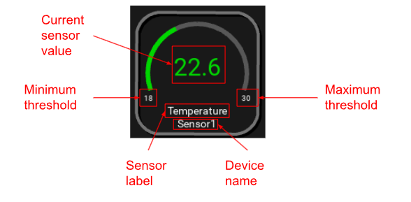
¶ Gauge Layout:
Note:
- Only Sensors on the Selected Tab will display Device names.
¶ Gauges with only Min and Max thresholds:
¶ Gauges with Indices:
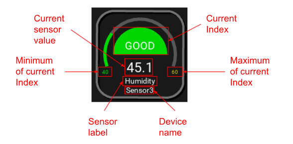
Setting maximum and minimum Alarm Thresholds on Sensors with indices are not shown on Gauges in the same way as Gauges without indices. The value displayed on Gauge with indices will display which value at which the next color step will change. If the Sensor data is greater than or equal to the maximum Threshold, the color of the Sensor value will change to red; if the Sensor data is less than the minimum Threshold, the color of the Sensor value will change to orange; otherwise the color of the Sensor value is white.
Definitions, ranges, and colors of indices are based on standardized information as described in the chart below and cannot be changed.

¶ Sensor Graphs:
Press any Gauge icon to load a Sensor Graph.
Note:
- Due to hardware limitations and performance, the Graph can only show historical data within a specific period of time (usually one hour or 30 minutes). This is dependent on the amount of data recorded.
Note:
- Previously recorded test data can be loaded in any duration from the local SD card.
Select whether to show Real-Time* data or previously recorded Test data in the upper right corner.
Note:
- Tests must be finished to view the data. Historical test data cannot be viewed if the recorded test has been deleted, or no tests have been run yet.
To close the Graph, press the Dismiss button.

*DISCLAIMER: SWRM only provides Near-Real-Time data.
¶ Alarm:
The Alarm is a feature of the SWRM Console. It will always present itself visually, but can be set up as an audible Alarm too, if the correct hardware is built into the Console.
The Alarm will be triggered if:
- Sensor data is greater than, or equal to the maximum Threshold.
- Sensor data is less than the minimum Threshold.
Example: If the minimum Threshold is 0 and the Sensor value is also 0, the Alarm will not be triggered.
Note:
- The Alarm feature cannot be fully disabled at this time.
¶ Triggered Alarms:
When the Alarm becomes triggered, the border around the triggered Gauge changes from gray to red.
If Sensor data then returns to a value within the safe Threshold, the audible Alarm will turn off (if applicable) and the border of the triggered Gauge will change to dim red. This is designed to indicate which Gauge had triggered the Alarm if the user was not there to see it.
- The border will return to gray if:
- The user opens the data Graph of the triggered Sensor.
- The user presses the Alarm Button when it is in normal status to reset all Gauges’ borders.
¶ Thresholds:
Maximum and Minimum Thresholds are used to trigger the Alarm in the event that Sensor data exceeds the set Threshold. While viewing a Graph (see example above), the dotted red horizontal line represents the maximum Threshold, and the dotted yellow horizontal line represents the minimum Threshold.
Changing the Threshold can be done in 3 different ways:
- Tap the text input entry on the right side of Maximum Threshold or Minimum Threshold fields to load a virtual keyboard, then type an integer number to set the new Threshold value.
- Press and hold the number between the up and down arrows, and slide up or down to increase or decrease the Threshold number.
- Tap the up arrow or the down arrow to add or subtract the Threshold value by one.
After the Threshold is changed, the Save button must be pressed to apply the new Thresholds before dismissing the Graph screen.
¶ Alarm Button:
If an Alarm triggers, the Alarm Button turns to red and the audible Alarm will sound (if applicable). Press the Alarm Button to turn OFF the audible alarm. The Alarm will trigger again as soon as the next Sensor value exceeds its boundaries. If all Sensor values return within their Thresholds, the Alarm will turn off automatically.

¶ Alarm Switch:
Some SWRM Consoles are designed to be equipped with an Alarm switch. In the event they are, the audible Alarm can be disabled using the Alarm switch on the Console. While in the OFF position, the Alarm will not audibly sound, but all warnings on the display will continue to function as described in the previous step.

¶ Control Panel:
The Control panel is located on the right side of the Console display, beneath the Settings button.

¶ Test buttons:
Test information is used to recall specific periods of time in Graphs or can be output to USB.
Pressing the Start Test button will begin logging task information that will be displayed on the left side of the Settings button.

Pressing the Stop Test button displays previous task information on the left side of the Settings button.

¶ Relay Buttons:
Relay Buttons manually control each of the (up to six) connected Relays. Relay Button’s names can be changed in the Routine Configuration Tab to assign a more meaningful name rather than Relay 1, Relay 2, etc.
When a Relay Button is pressed, it highlights blue to indicate that Relay is ON, when the Button is pressed again the Relay is turned OFF. Pressing the Turn Off All Relays Button will turn OFF all the Relays at once.
¶ Settings:
The Settings button is located on the top right corner of the screen. When the button is pressed, it highlights blue and displays Program Information to the left of the button, and opens Configuration Tabs below.

¶ Program Information:
Program Information includes current program version hash code, the date the program version was created, local IP address, and the expired SWRM client date and time.
¶ Configuration Tabs:
Configuration Tabs include Routines, Devices, Tune, and Settings.
Note:
- Due to size limitations on the display, not all Configuration Tabs may be displayed. Configuration Tabs can be scrolled by pressing and holding on any of the Configuration Tabs and dragging left or right.
¶ Routines Configuration Tab:
Functions:
¶ Relay Rules

A Relay Ruleis surrounded by a white rectangle box. When a rule is added, it is disabled by default. Rules can only be edited while disabled. Select the Relay, Relay State (on or off), Sensor, Device, Condition and Sensor value to create the Relay Rule.

To setup a Rule:
- at
- Select the Device(s) that will be the trigger source.
- Selecting “any Device” means the Sensor value on any one Device will trigger the Rule.
- Selecting “every Device” means all values of the same Sensor on all Devices will trigger the Rule.
- Selecting “Sensor 1,2 or 3” means only that Sensor can trigger the Rule.
- when
- Select the Sensor that will be the trigger.
- turn
- is
- > Greater than
- >= Greater than or equal to
- < Less than
- <= Less than or equal to
- Activate the checkbox in the top left corner to enable the Rule.
When the Rule is enabled, the first line will change to Rule #N is enabled , and the checkbox is shown as checked while others change to locked status. A Rule cannot be modified while it is enabled. Unchecking the box will disable the Rule and allow the user to modify or remove the Rule.
Note:
- When Rules are enabled, they will work only after new Sensor data is detected. This means the Rules will not trigger Relays depending on previous Sensor values.
¶ Relay Timer:

Relay Timers are surrounded by a white rectangle box. Press the Add a Step button to add a step block at the end, or press Remove a Step button to remove the last step block.

Select which Relays will be turned on for that step, and set how many seconds the Timer will be active. The default active period is 60 seconds for each step.
Note:
- Selecting no Relays will still activate the step, which is useful for creating Timers between steps.
The entire Routine with all the steps will start immediately after pressing the Run button. The Run button will highlight blue, indicating it is active. The progress bar beneath the Run button will display the names of current active Relays and duration of the Routine.

To halt the Routine when it is running, press the Run button again, or press the Turn Off All Relays Button in the control panel.The Relays’ Routine will stop running when it has been halted. Pressing the Run button once again will run the entire Routine from beginning.
¶ Devices Configuration Tab:
Functions:

¶ Sensor Board Names:
Sensor Board names can be changed in the Configuration Panel by pressing the Edit Device Name button.

¶ Tune Configuration Tab:
Function:
Used for calibrating same-Sensors on different Devices.

If different values on multiple Sensor Boards are being measured during calibration, an offset can be applied to narrow the gap in Sensor values. By inputting a number associated with the Sensor being calibrated, then activating the checkbox, an offset will be applied to each same-Sensor connected to the Console. The value entered should be taken from a known value or one taken from another calibrated measuring Device.
Note:
- Some variation between Sensor data can still be expected following calibration on Sensors that measure in extremely small numbers such as PPM and PPB, even if they are measured right beside each other.
¶ Settings Configuration Tab:
Additional Settings located in the Settings panel.
¶ WiFi settings:
Connecting the WiFi and internet is necessary for the Console to send data to the SWRM Dashboard as well as fetch new versions.

¶ Outputting Sensor Data:
Sensor data can be transferred from the Console by plugging in a USB stick and pressing the Output CSV to USB button. Data files transferred to the USB stick are in CSV format.
Note:
- Wait for the notice stating users can safely unplug the USB stick before removing the USB stick.

CSV files are named by Device name and Sensor Board label. They contain all data saved locally. Press the Delete Local Data button to remove old Sensor data from the CSV files.
The program collects and records Sensor data to local disk. If local saved data is occupying too much disk space and impairing computer performance, press the Delete Local Data button to remove saved Sensor data, test data and logs. Settings like WiFi information, Relay Button names, or Device names, will not be removed.
¶ Report to Server:
*This function is built into the Console but is not operational.
Pressing these buttons will generate metrics reports which will be sent to the SWRM Dashboard directly.

Users can press the Report Logging Info button to upload a local log file to the SWRM server for debugging.
¶ Updates:
After any firmware update or system update, rebooting the Console is strongly recommended.

¶ Powering Off & Rebooting
WARNING!:
Cutting power to the Console while the unit is powered ON may corrupt the operating system. It is recommended the Console be connected to a battery backup in case a power outage occurs.
NOTE:
- Some Sensors have heating elements that need to get up to temperature before providing accurate readings. If Sensors are ever powered down, they will need to remain OFF for a minimum of 20 seconds. Elements will need to reheat for a minimum of 15 minutes after power is restored before providing accurate Sensor readings.Console and Sensor power can be turned off in a variety of ways but is recommended to leave them powered on when not in use.
- Power Off: Turns off the Console and Sensors.
- Reboot: Safely reboots the Console and Sensors.

¶ Recovery Mode
If the Console crashes, a recovery program will start automatically as shown below. Generally, if the main program crashes due to a minor reason/operation which does not influence the main operation of the program, please press the Power Off button and then restart the Device; if the main program crashes in a way that it cannot fulfill its main functionalities, please press the Roll back to previous version button and then restart the Device; if rolling back to previous version still does not work or users want to remove all custom information on the Device, please press the Reset to Factory Mode button. In either case, please Contact Support and report the situation as clearly as possible so that we can work to fix the bug and release a new version of the program.
